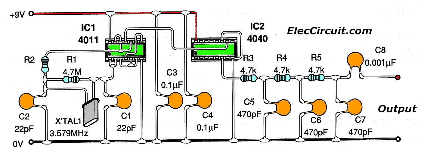
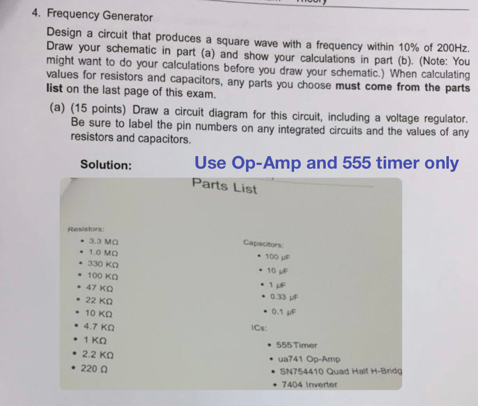
Simple IF signal generator circuit using CMOS IC Circuit Diagram How to Calibrate. The 50 Hz being generated from pin 1. Hobbyists possessing a frequency meter can easily calibrate this crystal controlled time base generator circuit by merely hooking up the meter to pin 7 of IC1 (Q4) and fine-tuning C2 until a display of 204.800 Hz is seen on the meter.
In the video, I will show you how to DIY a simple frequency generator or oscillator by using IC NE555 and a few common parts. Step by step in details.
9 Simple Sine Wave Generator Circuits Explored Circuit Diagram
In today's video we learn how to make a frequency / tone generator out of simple parts that can be easily obtained, this is a great project for a starter to WHAT IS THISLearn how to make a DIY frequency generator circuit using only a couple of components. RESOURCES Frequency Generator Schematic - https://drive

1) Using IC 4049. Using only one low-cost CMOS IC 4049 and a handful of separate modules, it is easy to create a robust function generator that will provide a range of three waveforms around and beyond the audio spectrum.. The purpose of the article was to create a basic, cost-effective, open source frequency generator that is easy to construct and used by all hobbyists and lab professionals. This is a simple function generator that works in the audio frequency range. It can be useful for amplifier testing, experimentation in DSP. LOGIN Author's prototype for Arduino based frequency generator. Circuit diagram of the sine, square and ramp Arduino-based frequency generator is shown in Fig. 2. It is built around an Ardunio Uno

Simple Function Generator : 5 Steps Circuit Diagram
The bridge circuit is C1 R4a and C3 R4b. R4 is a dual-ganged potentiometer and controls the frequency, which is 1/2πRC. Assuming R4 is central, say 2k, this would be 1/(2*π* 5k * 0.01u) = 3kHz. The lamp is a small 12V incandescent light bulb.As the filament heats up, its resistance goes up, reducing the current through it, reducing the gain and amplitude at the output, so you have a very
