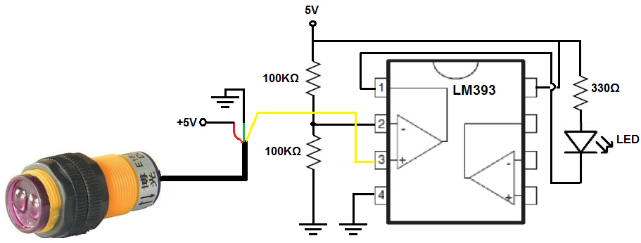
Infrared Proximity Sensor Wiring Diagram Circuit Diagram A tutorial on How to make an InfraRed (IR) proximity sensor circuit along with detailed explanation on how the circuit works. The sensitivity or Range of detection can also be controlled by adjusting the potentiometer. IR (InfraRed) proximity sensor / Obstacle detector circuit using LM358 opamp. LED chaser circuit / Sequential LED flasher
Security Systems: IR sensors can detect movement and trigger alarms in security applications. Industrial Automation: Factories use IR sensors for object counting, positioning, and proximity detection in conveyor systems. Smart Home Applications: IR sensors contribute to energy-efficient lighting systems that turn on/off based on occupancy

IR (InfraRed) proximity sensor / Obstacle detector circuit using LM358 ... Circuit Diagram
Infrared sensors are used in a wide range of applications including here proximity robotic applications for distance and object detection, or color detection and tracking. As a disadvantage, I have to mention that IR sensors have bad performance in strong sunlight and many applications where this type of sensor is used are designed for indoor use.

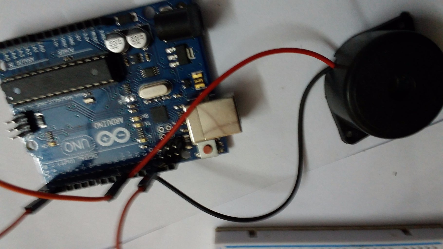
Overview. In this guide, we will explore the interfacing of an IR Sensor Module with an Arduino UNO R4 Minima Board. An IR (Infrared) Sensor Module is a device designed to detect infrared light, commonly used in remote control systems, proximity sensors, and line-following robots.. The IR Sensor Module typically includes an infrared transmitter and receiver. Infrared Proximity Sensors can be used for different types of applications like obstacle sensing, color detection, fire detection, line sensing, etc, and also as an encoder sensor. The sensor provides a digital output of 5v DC when there is an object in front of the sensor. Today in this tutorial we are going to show step by step how to interface this Infrared Proximity Sensor with Arduino

Detecting Objects Using the Infrared(IR) Obstacle Sensor Circuit Diagram
VCC: Connects to a 5V or 3.3V or a microcontroller or a power supply. GND: Connects to ground. OUT: Digital output that goes HIGH or LOW based on obstacle detection. How the IR Sensor Works. The IR LED continuously emits infrared light. When an object comes into the range of the sensor, the infrared light reflects off the object and is detected by the photodiode.